

- Home >
- Products >
- Technical Highlight >
- Vol.21: TRUSTARC™ DW-A62LSR(A5.29 E91T1-GM) improves notch toughness of HSLA weld metal after PWHT
Technical Highlight Vol.21
Vol.21: TRUSTARC™ DW-A62LSR(A5.29 E91T1-GM) improves notch toughness of HSLA weld metal after PWHT

In the construction of structures such as spherical tanks and pressure vessels, weldments are subjected to postweld heat treatment (PWHT) in order to reduce the residual stresses induced by welding and for improving the fracture toughness and fatigue properties of the welds. As these structures have grown larger in size and are being operated at even-higher pressures, in tandem with recent growth in energy demand, the steel materials used have been increasingly strengthened. To company with such a trend, TRUSTARC™ DW-A62LSR, a rutile type flux cored wire (FCW) for HT610 or higher class steel materials, has been developed and confirmed to satisfy the following requirements:
As welded:TS≧621MPa (90ksi), vE≧27J at-60℃
PWHT: TS≧586MPa (85ksi), vE≧27J at-40℃
Table 1 shows the typical chemical compositions of deposited metal with TRUSTARC™ DW-A62LSR.
| C | Si | Mn | P | S | Ni | Others |
|---|---|---|---|---|---|---|
| 0.05 | 1.14 | 1.29 | 0.007 | 0.008 | 2.59 | Mo, Ti, B |
Figures 1 and 2 show the relationship between PWHT conditions and mechanical properties of the deposited metal.
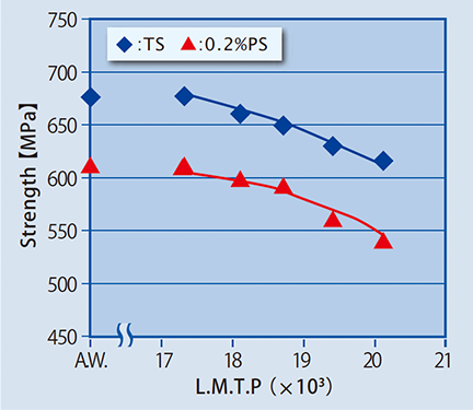
Figure1: Relationship between tensile strength and the Larson Miller's Temper Parameter (LMTP)
LMTP=T (20+log t).
(T: Temperature [K]; t:holding time [hour])
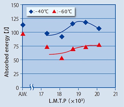
Figure2: Relationship between absorbed
energy and LMTP
The effect of heat input (cooling rate at 540℃ [℃/sec], calculated by Rosenthal's equation) on the tensile strength and absorbed energy of deposited metal in as welded and PWHT conditions was studied and the results are shown in Figures 3 and 4, respectively.
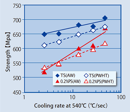
Figure3: Relationship between tensile strength and cooling rate at 540℃ in as welded and PWHT (620℃×8hours; LMTP=18.7×10³)conditions Solid line: as-welded; Dotted line:PWHT
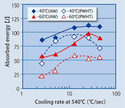
Figure4: Relationship between absorbed energy and cooling rate at 540℃ in as welded and PWHT (620℃×8hours; LMTP=18.7×10³)conditions Solid line: as-welded; Dotted line:PWHT
A butt joint weld test was conducted under the conditions shown in Table2.
| Welding wire | DW-A62LSR (1.2mmΦ) |
|---|---|
| Base metal | TS610MPa class steel (60mm thick) |
| Dimension of groove |
|
| Welding position & parameters(heat input) |
(1) Flat (1G): 270A-28V (1.2 kJ/mm) (2) Horizontal (2G): 260A-28V (0.8 kJ/mm) (3) Vertical-up (3G): 220A-24V (2.4 kJ/mm) |
| PWHT | As welded & 620℃x 8 hours (LMTP18.7x10³) |
| Preheating & interpass temperature | 90-110℃ and 140-160℃ |
| Shielding gas | 80%Ar-20%CO2; 25 liter/min |
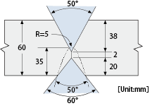
Figure 5 shows the macrostructures of the welded joints in 1G, 2G and 3G positions. The test results of mechanical properties in as welded and PWHT conditions are shown in Tables 3.
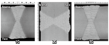
Figure5: Macrostructure of welded joints (1G,2G and 3G positions from the left to the right)
| Position | PWHT condition |
Tensile properties | Notch toughness | ||||
|---|---|---|---|---|---|---|---|
| 0.2%PS [MPa] |
TS [MPa] |
El [%] |
Absorbed energy [J] | ||||
| -60℃ | -40℃ | ||||||
| 1G | AW *1 | 713 | 748 | 22 | 67 | 81 | |
| PWHT *2 | 627 | 692 | 22 | 41 | 61 | ||
| 2G | AW *1 | 722 | 752 | 22 | 81 | 91 | |
| PWHT *2 | 678 | 721 | 27 | 47 | 62 | ||
| 3G | AW *1 | 640 | 706 | 24 | 61 | 90 | |
| PWHT *2 | 619 | 686 | 28 | 31 | 64 | ||
*1 AW: as welded *2 PWHT: 620℃ x 8 hours
Products
- Main Products
- Welding Consumables
- Arc welding robots
- Industries - Recommended Materials
- Welding Handbook Quick View
- Product Quick View & Highlights
- For HEAT-RESISTANT STEEL
- For STAINLESS STEEL
- For LOW-TEMPERATURE STEEL
- Product Highlight
- Catalog
- Technical Highlights
- Certification
- SDS ※English Only
- ARCMAN
- Welding Robot
- Software